
CCU 12V Series
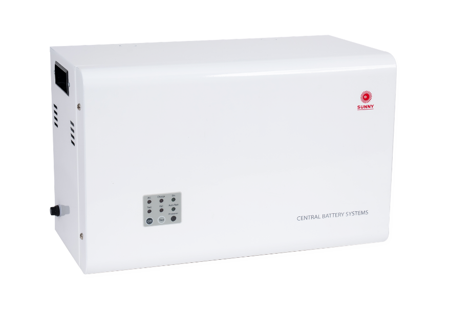
Our Products / Central Battery Systems / CCU 12V Series (Figure A)
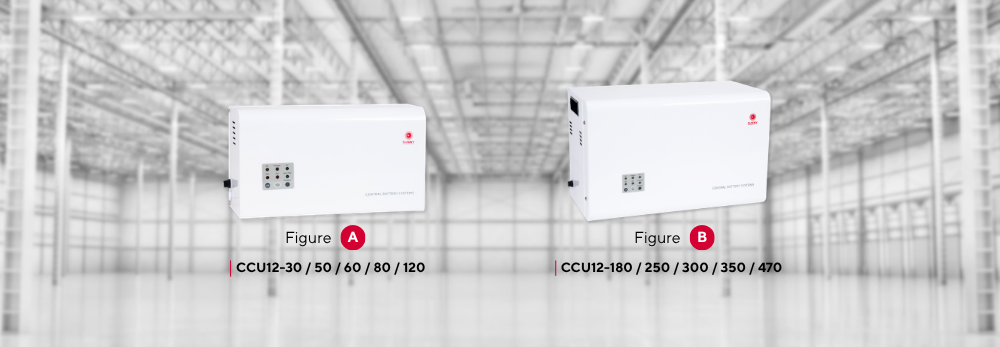
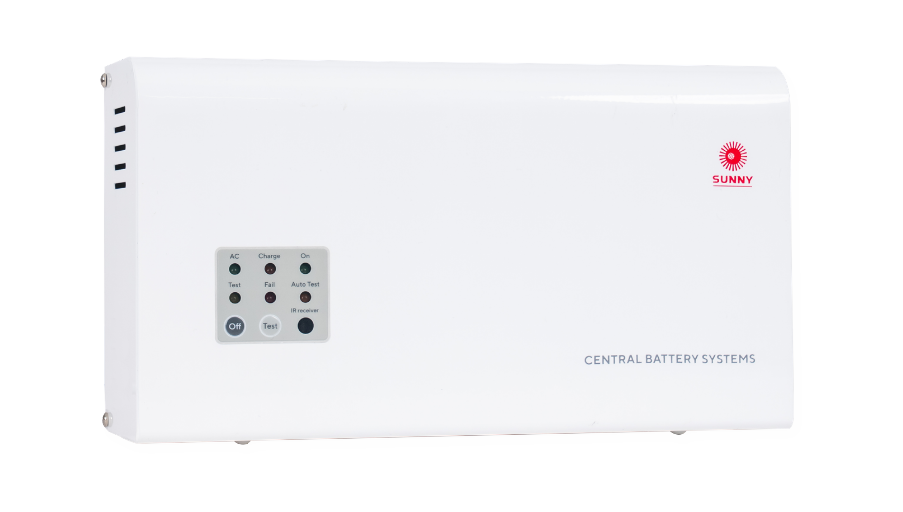
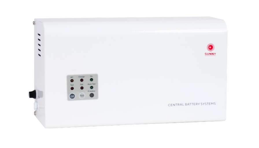
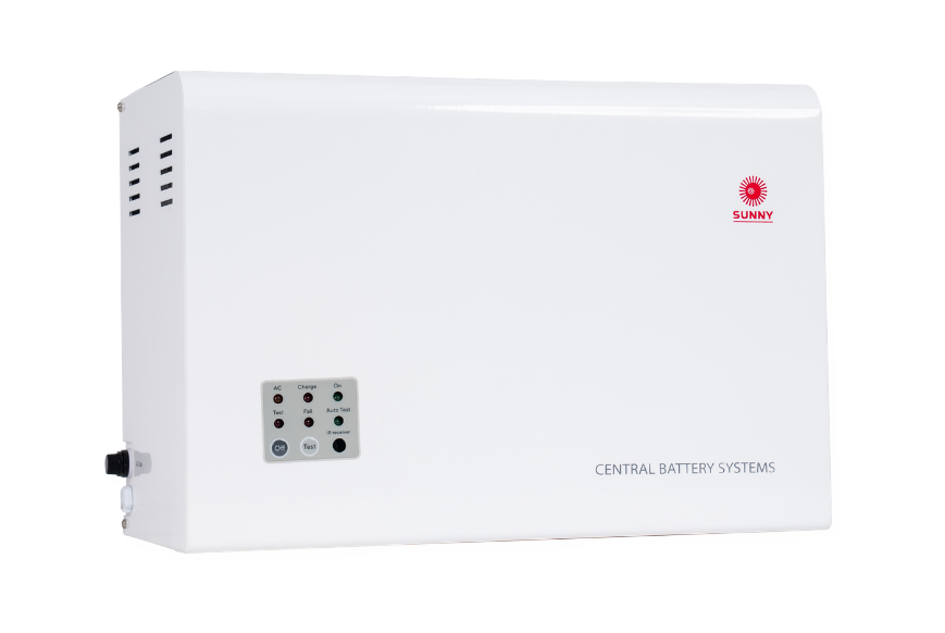
Central Battery Control Unit CCU 12V Series
Central Battery Systems CCU 12V Series is a central emergency lighting control unit for a 12VDC system, designed to supply power to emergency lighting lamps when the main power fails. The system automatically controls lamp operation to ensure continuous illumination, helping improve evacuation safety inside buildings.
The unit is equipped with a Sealed Lead-Acid Maintenance Free (SLA) battery, together with a 3-Step Charger System and a built-in monitoring system for both voltage and battery status, enhancing safety and extending the service life of the system.
In addition, the CCU 12V Series comes with Auto Test and Remote Test functions for convenient inspection and maintenance, reducing the burden of regular maintenance and increasing operational reliability. The enclosure is made of electro-galvanized steel coated with epoxy powder coating, providing strength and corrosion resistance. It is suitable for indoor installation and professional-grade emergency lighting systems.
Technical Specifications
Mode of Operation | Non-Maintained |
Operating Temperature | 10 to 50°C |
Input Voltage | 220-240VAC / 50Hz |
Output Voltage | 12VDC |
Load Capacity | 30W / 50W / 60W / 80W / 120W / 180W / 250W / 300W / 350W / 470W (10 options) |
Battery Type | Sealed Lead-Acid Maintained Free |
Protection Features | • AC, DC Fuse • AC Under Voltage Protection • Battery Low Voltage Cut-Off |
Testing Systems | • Auto Test • Manual Test or Remote Test |
Charging Method | 3 Steps Charger System |
Charging Period | 10-15 Hrs |
Backup Time | 2.0 Hrs |
Housing | Electro-galvanized steel sheet 1.0mm. thick with epoxy powder coating |
Weight | 4.00 – 40.00 Kg |
Degree of Protection | IP20 |
Mounting | Wall Surface |
Accessory | Infrared Remote Test (RT-S3) |
Features
- Battery
- Use Sealed Lead-Acid Maintained Free (SLA), backup power for 2 hours.
- Functions
- Auto Test schedule: 1 month every 60 seconds, 1 year every 120 minutes (according to standard EIT.021004-22), activate and deactivate functions with a remote control.
- The operation can be tested manually (Manual Test).
- A 5-second, 30-minute or 60-minute self-test can be performed on the unit using the remote
- Circuit Systems
- Controlled by an 8-bit microcontroller circuit
- Under Voltage Operation System
- Protection Features
- AC and DC fuse to prevent current overload
- Surge Protection
- IP20 dust and water resistant
- Features to Extend Battery Life
- An innovative 3 Steps Charger System
- A Low Voltage Cut-Off to prevent the battery from draining completely
- Warning Systems
- Alerts when the automatic battery test (Auto Test) detects that the central battery emergency backup system provides less than 120 minutes of lighting backup (Battery Fail).
- Indicate that there is a problem charging the battery (Charging Fail).
User Manual & Demonstration VDO
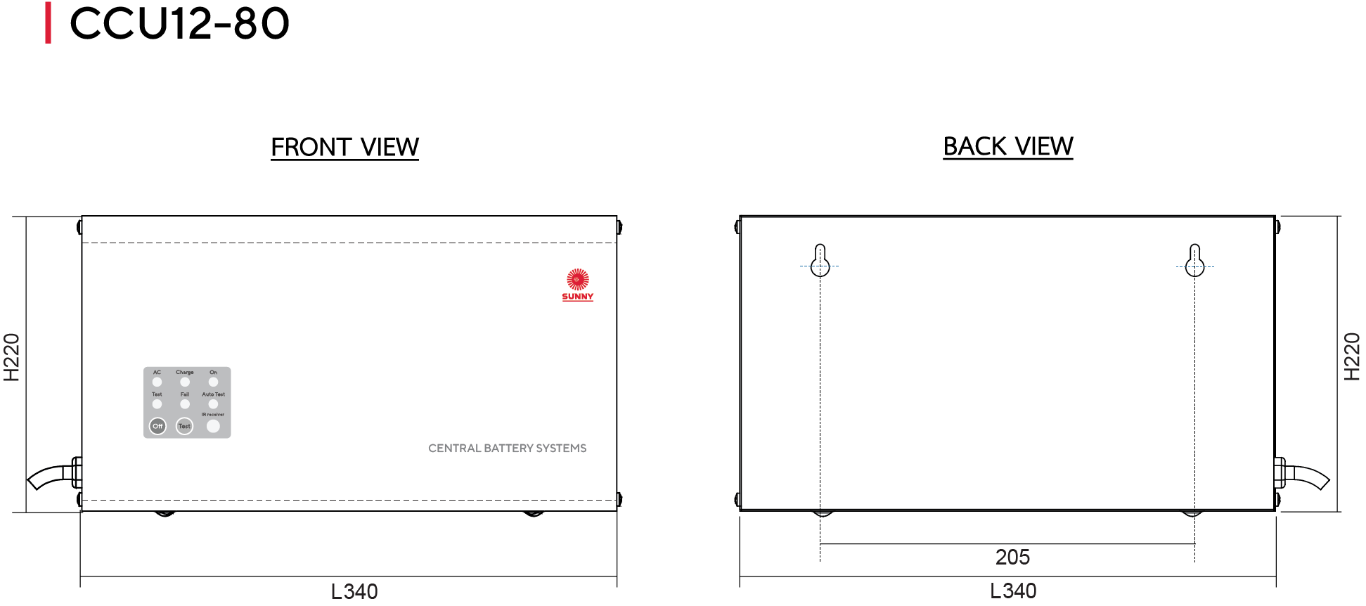
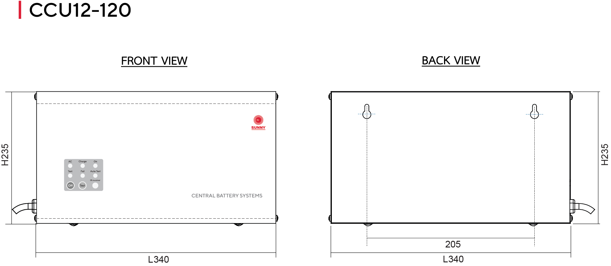
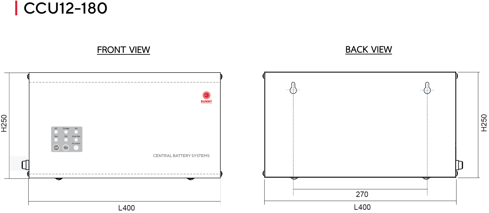
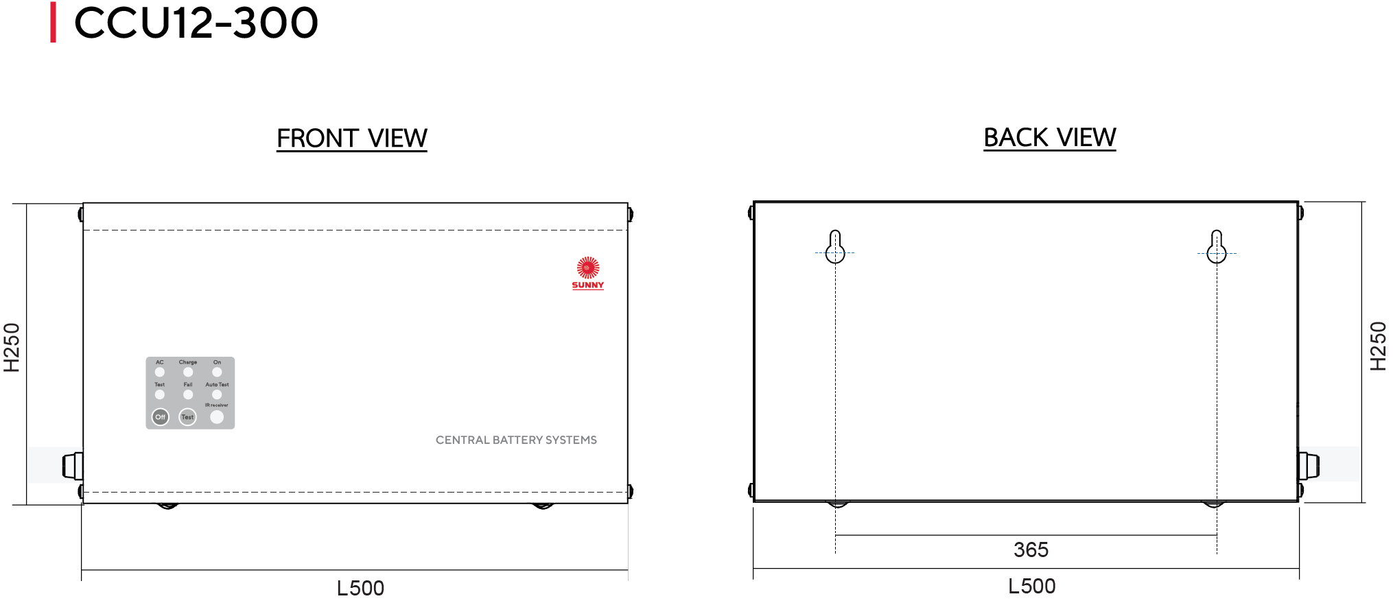
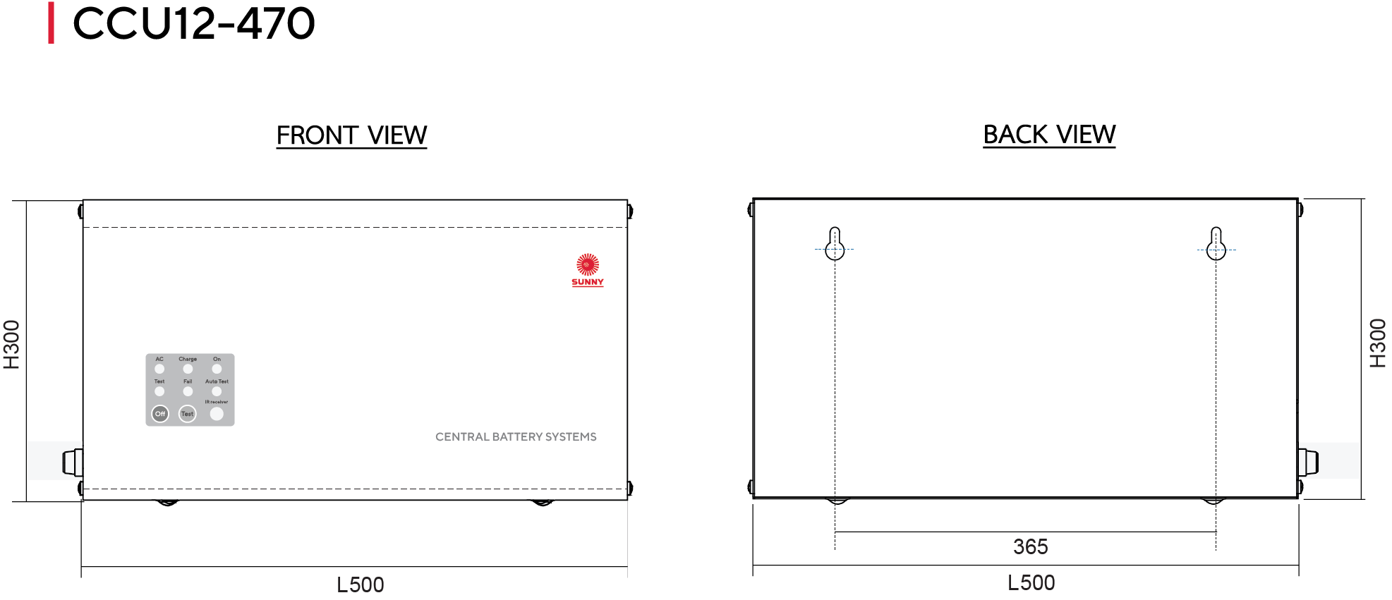
Indicators - Figure A
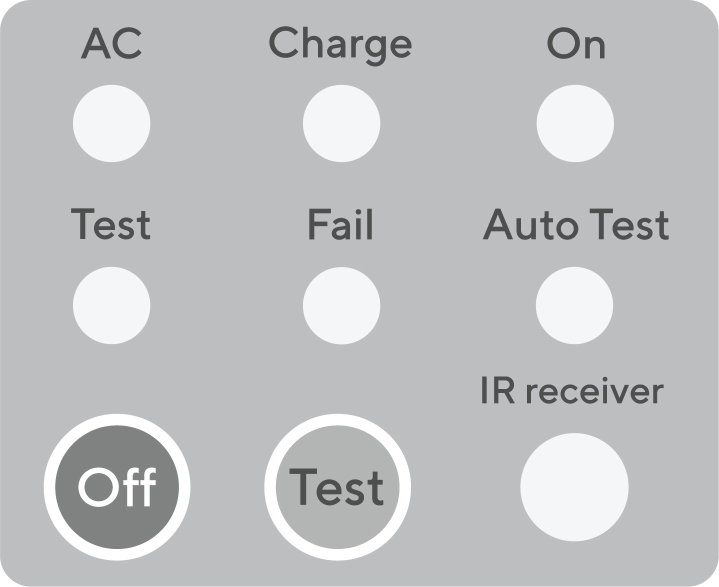
LED AC | Indicates that the unit is receiving a power supply |
LED Charge | Indicating charging status. |
LED On | Indicates that the unit is receiving a power |
LED Test | Indicates that the unit is in test mode. |
LED Fail | Indicates that the unit is a problem with the battery |
LED Auto Test | Indicates automatic testing status. |
Switch Off | Press to turn off the lamp and the system of the unit (while the power is off or the unit is not plugged in) |
Switch Test | Press to test the device’s availability (during normal circumstance and the unit is plugged in) |
IR receiver | Infrared signal receiver |
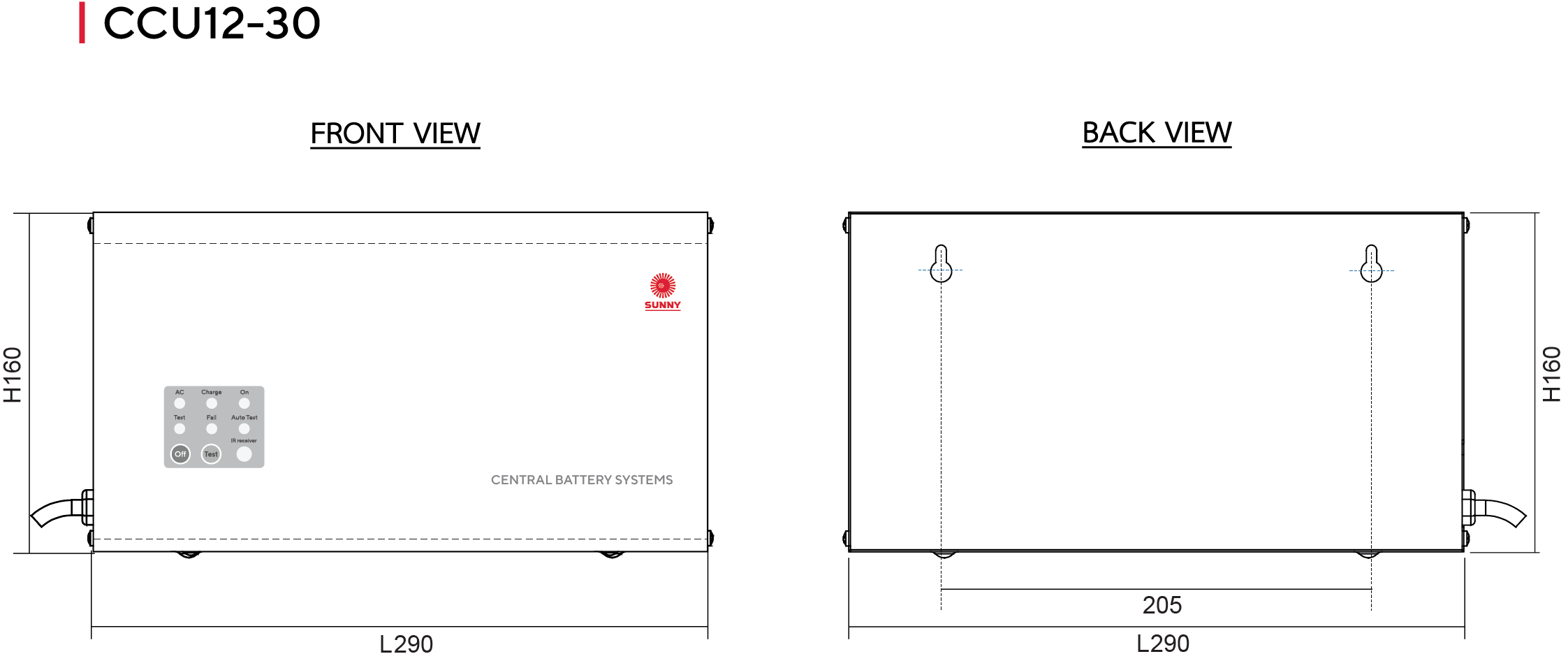
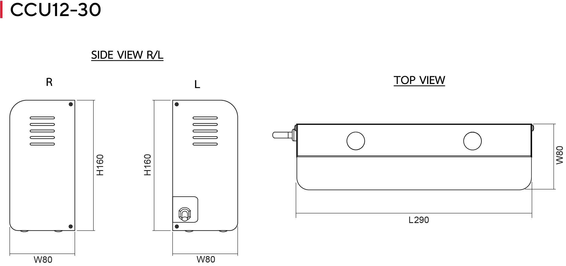
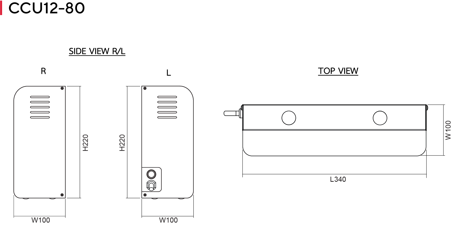
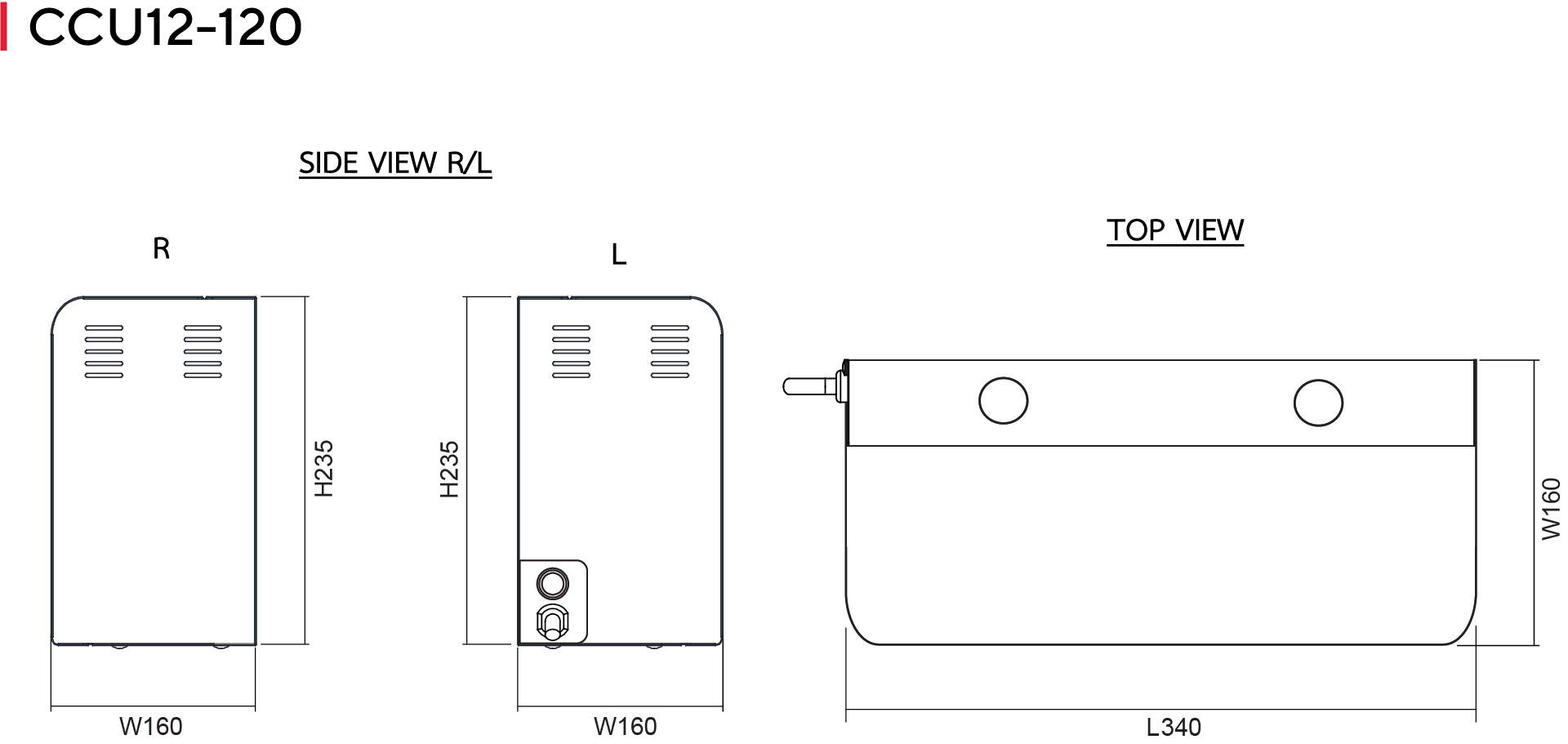
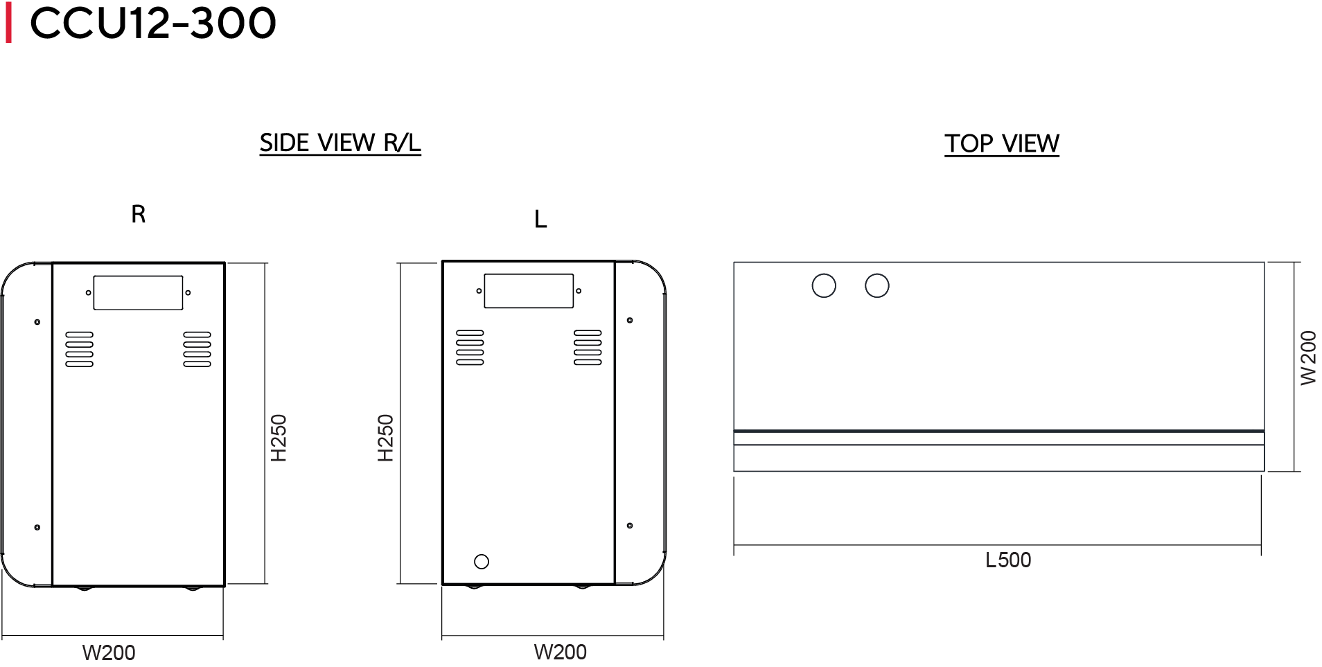
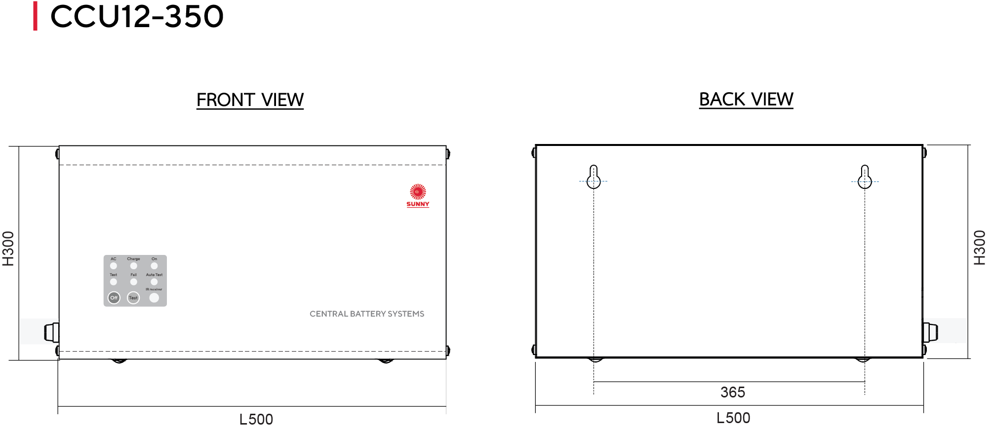
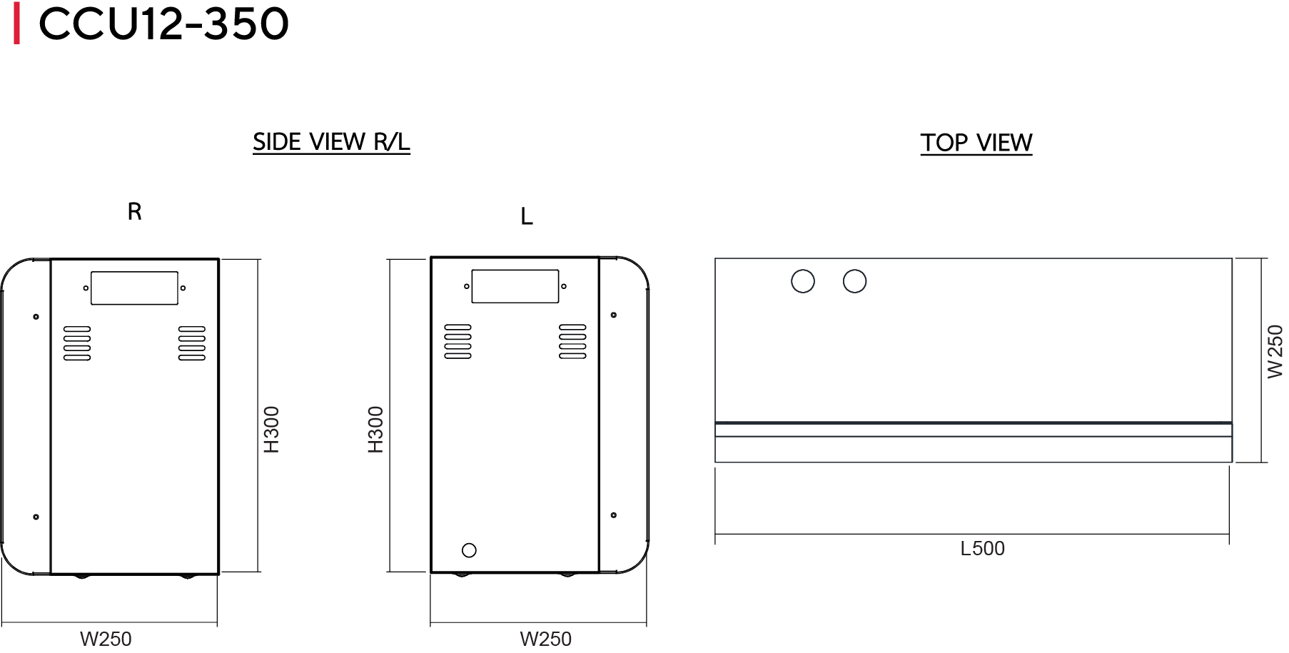
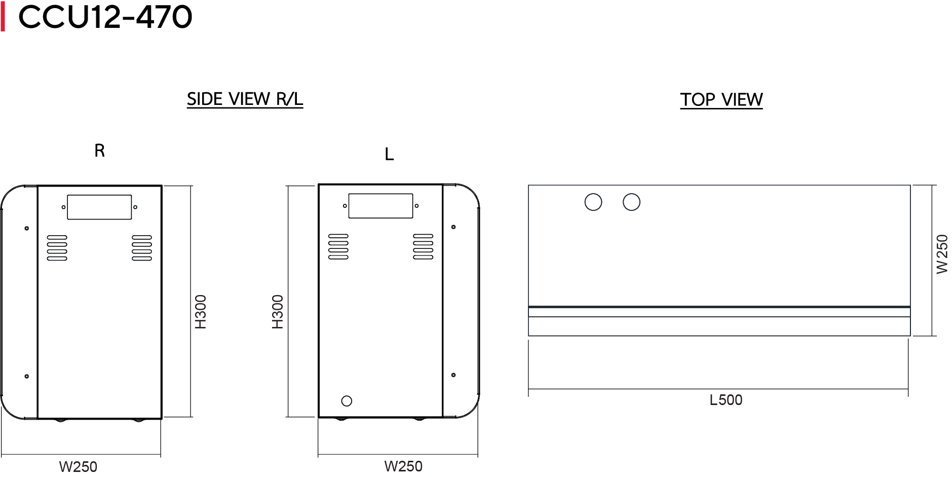
Dimensions (mm) - Figure A
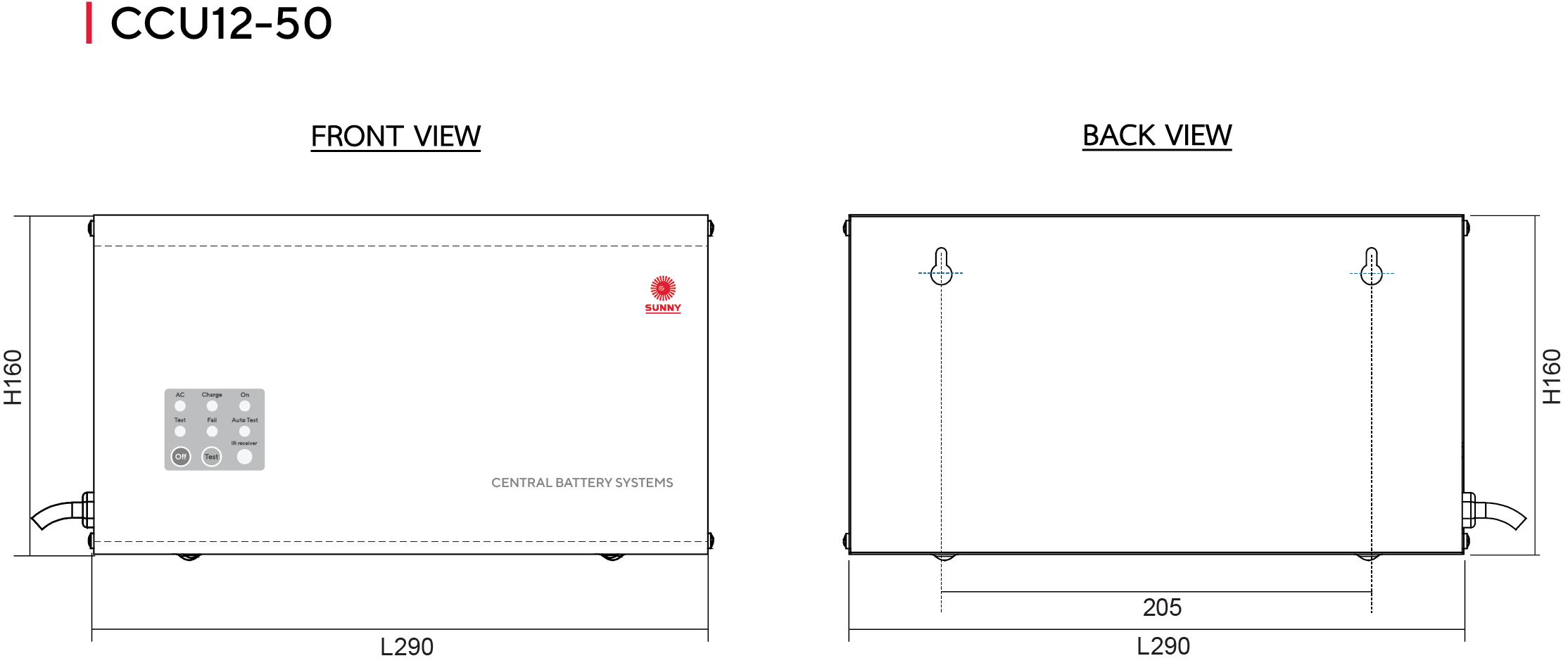
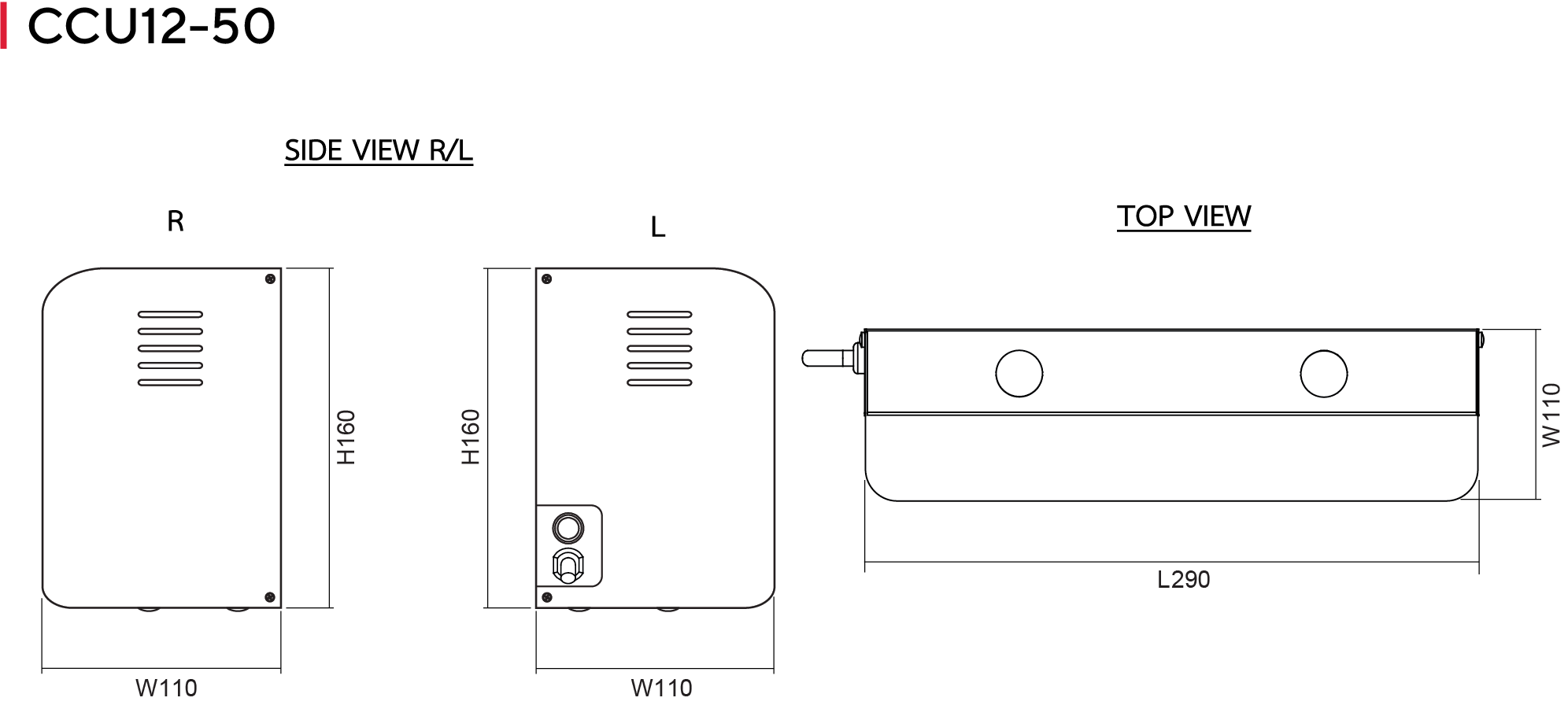
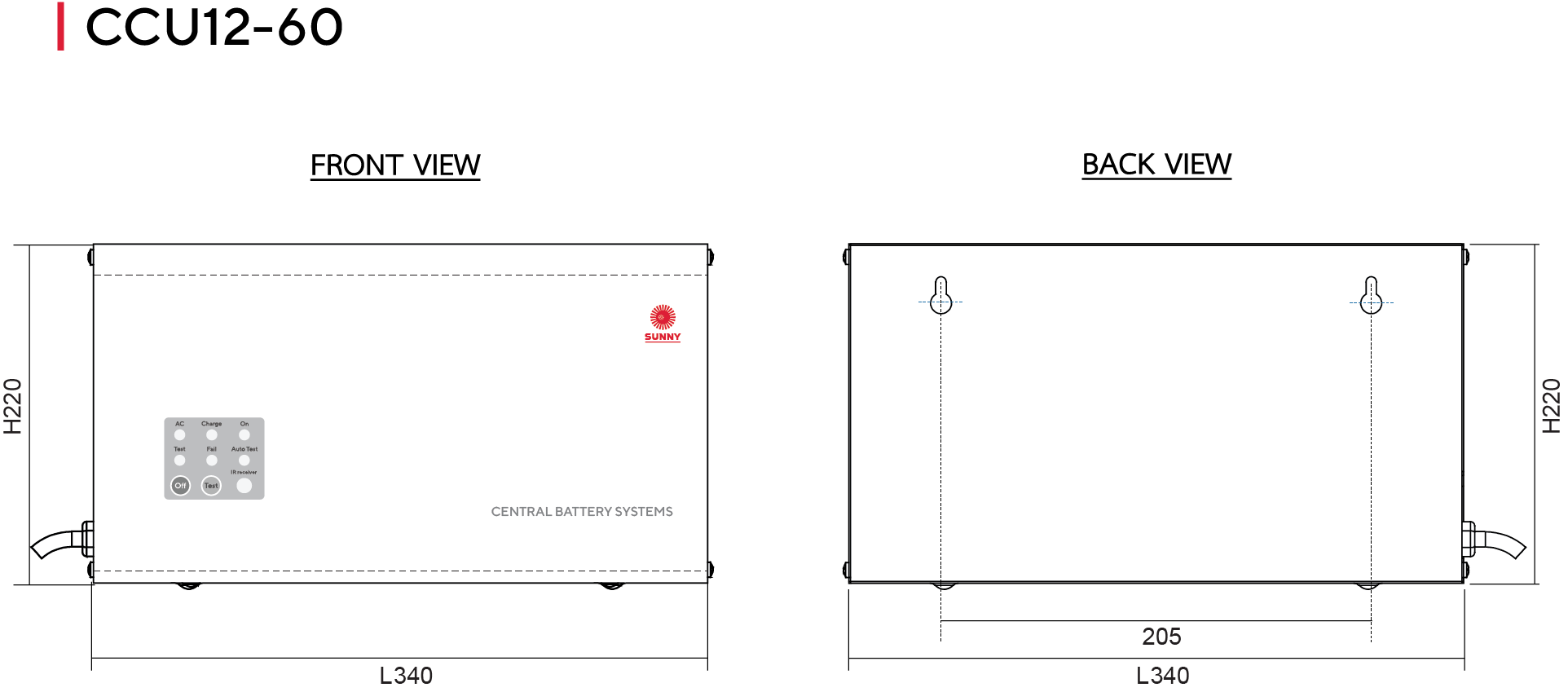
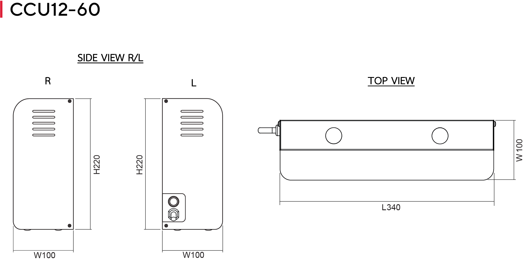
Indicators - Figure B
LED AC | Indicates that the unit is receiving a power supply |
LED Charge | Indicating charging status. |
LED On | Indicates that the unit is receiving a power |
LED Test | Indicates that the unit is in test mode. |
LED Fail | Indicates that the unit is a problem with the battery |
LED Auto Test | Indicates automatic testing status. |
Switch Off | Press to turn off the lamp and the system of the unit (while the power is off or the unit is not plugged in) |
Switch Test | Press to test the device’s availability (during normal circumstance and the unit is plugged in) |
IR receiver | Infrared signal receiver |
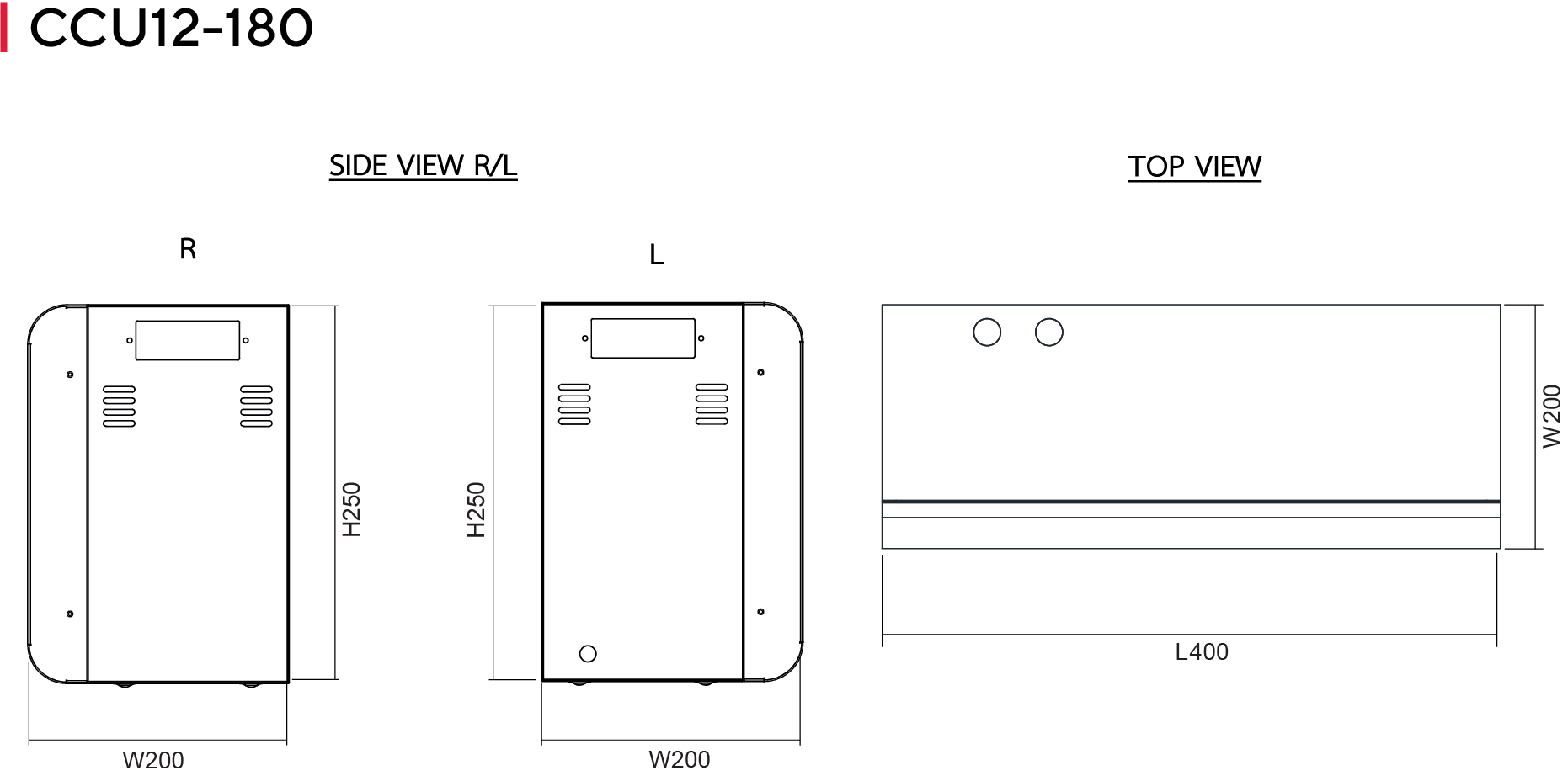
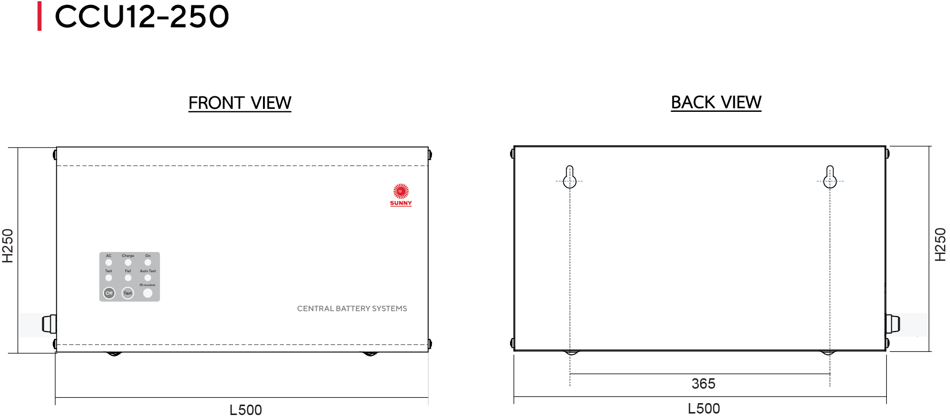
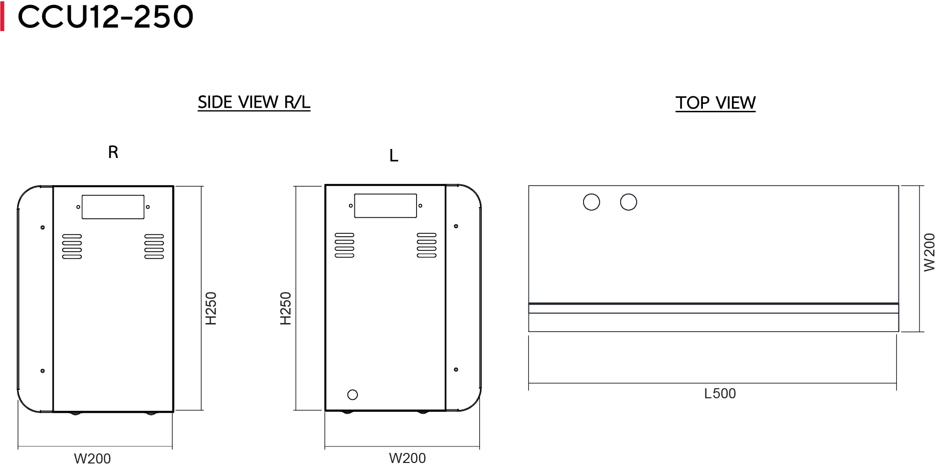
Dimensions (mm) - Figure B
CCU 12V Series | Spec Sheets
Model | Output Voltage | Maximum Power Load | Battery Capacity | Back up (hr.) | LxWxH (mm) | Weight (kgs.) | Figure |
|---|---|---|---|---|---|---|---|
CCU 12-30 | 12VDC | 30W | 12V – 7.0Ah | 2 | 290x80x160 | 4 | A |
CCU 12-50 | 12VDC | 50W | 12V – 12Ah | 2 | 290x110x160 | 6.1 | A |
CCU 12-60 | 12VDC | 60W | 12V -15Ah | 2 | 340x100x220 | 7.15 | A |
CCU 12-80 | 12VDC | 80W | 12V – 18Ah | 2 | 340x100x220 | 8 | A |
CCU 12-120 | 12VDC | 120W | 12V – 26Ah | 2 | 340x160x235 | 13 | A |
CCU 12-180 | 12VDC | 180W | 12V – 40Ah | 2 | 400x200x250 | 18.5 | B |
CCU 12-250 | 12VDC | 250W | 12V – 26Ahx2 | 2 | 500x200x250 | 25.32 | B |
CCU 12-300 | 12VDC | 300W | 12V – 65Ah | 2 | 500x200x250 | 30 | B |
CCU 12-350 | 12VDC | 350W | 12V – 40Ahx2 | 2 | 500x250x300 | 35.5 | B |
CCU 12-470 | 12VDC | 470W | 12V – 100Ah | 2 | 500x250x300 | 40 | B |